

Available 24/7 at
+86 13632816717

What is Aluminium Electrolytic Capacitor?
Aluminum electrolytic capacitors are widely used in electronic and electrical systems for power filtering, voltage smoothing, and energy storage. A chip aluminum electrolytic capacitor offers a compact solution for applications where space and reliable capacitance are important. With a wide range of specifications and applications, these capacitors are commonly used in power supplies, industrial equipment, automotive electronics, and consumer devices. This guide explores their key features, specifications and applications.
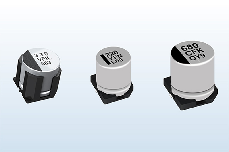
What is Aluminium Electrolytic Capacitor?
An aluminium electrolytic capacitor is a polarized capacitor that uses an aluminium oxide layer as its dielectric and an electrolyte as part of its internal structure. It is known for its relatively high capacitance and compact size, making it a common choice for storing electrical energy and filtering voltage in electronic circuits.
Aluminium electrolytic capacitors are widely used in power supplies, audio equipment, industrial control systems, automotive electronics, LED drivers, and other electronic devices. They are particularly suitable for applications that require high capacitance for voltage smoothing and ripple reduction.
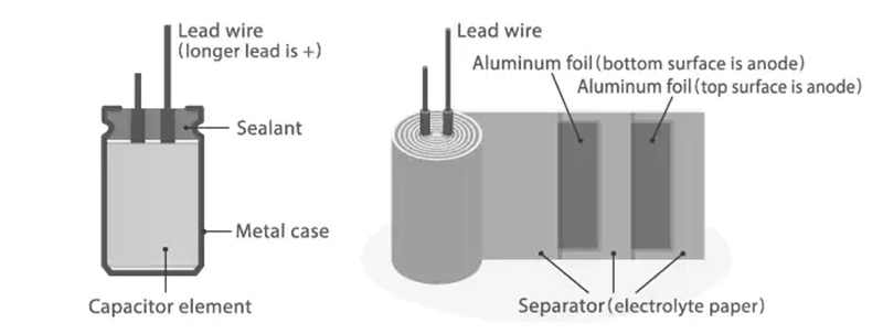
Structure of an Aluminium Electrolytic Capacitor
- Anode Foil: Specially treated aluminium foil that serves as one of the main electrodes of the capacitor.
- Aluminum Oxide Dielectric Layer: A very thin oxide film formed on the surface of the anode aluminium foil, which acts as the dielectric.
- Electrolyte: Functions as part of the cathode and forms the capacitive structure together with the aluminum oxide dielectric layer.
- Cathode Foil: Works together with the electrolyte to form the cathode.
- Separator Paper: Located between the anode and cathode foils. It separates the two aluminium foils while absorbing and retaining the electrolyte.
- Case and Seal: Usually made with an aluminium case and a rubber sealing plug or similar structure to enclose the internal components and prevent electrolyte leakage.
These materials typically undergo winding, impregnation, assembly, sealing, and aging processes to form the familiar cylindrical aluminium electrolytic capacitor. Its typical internal structure can be summarized as: Anode Aluminium Foil → Aluminum Oxide Dielectric Layer → Electrolyte → Cathode Aluminium Foil.
How Does an Aluminum Electrolytic Capacitor Work?
An aluminum electrolytic capacitor stores electrical energy through an electrochemical structure formed between its electrodes and dielectric layer. When a voltage is applied, the aluminum oxide layer on the anode foil acts as the dielectric, separating the anode from the electrolyte-based cathode. The extremely thin oxide layer allows the capacitor to achieve high capacitance in a relatively compact size.
The aluminum electrolytic capacitor working process can be explained in several simple steps:
Voltage Is Applied
When a DC voltage is connected, the positive terminal is connected to the anode aluminium foil, while the negative terminal is connected to the cathode.
Electric Field is Established
The applied voltage creates an electric field across the thin aluminum oxide dielectric layer on the anode foil. This oxide layer electrically separates the two electrodes.
Charge is Stored
Positive and negative charges accumulate on the corresponding electrodes. The aluminum oxide dielectric prevents direct current from flowing between them, allowing the capacitor to store electrical energy.
Capacitor is Fully Charged
As the capacitor charges, its voltage approaches the applied voltage. Under steady-state DC conditions, only a small leakage current continues to flow.
Energy is Released
When the circuit requires energy, the capacitor discharges through the connected load, releasing its stored electrical energy.
Filtering and Smoothing
In practical electronic circuits, an aluminum electrolytic capacitor can repeatedly charge and discharge to help smooth voltage fluctuations, reduce ripple, and stabilize the power supply.
In electronic applications, aluminum electrolytic capacitors are commonly used for power supply filtering, voltage smoothing, ripple reduction, and bulk energy storage. Because they are polarized, they must be connected with the correct positive and negative terminals.
Aluminum Electrolytic Capacitor Parameters
Rated Voltage: The rated voltage is the maximum continuous DC voltage that an electrolytic capacitor is designed to withstand under specified conditions. Common ratings include 6.3V, 10V, 16V, 25V, 35V, 50V, 100V, and higher. The applied voltage should generally remain below the rated voltage to prevent dielectric damage and premature failure.
Capacitance and Tolerance: Capacitance indicates the capacitor's ability to store electrical charge and is typically measured in µF (microfarads). Electrolytic capacitors are available in a wide range of capacitance values. Capacitance tolerance indicates how much the actual capacitance can vary from its nominal value, such as ±20%.
Equivalent Series Resistance (ESR) and Impedance: ESR represents the internal resistance of the capacitor and affects power loss, heat generation, and ripple-current performance. Lower ESR generally provides better efficiency and high-frequency performance. Impedance describes the capacitor's overall opposition to AC current and varies with frequency, temperature, and capacitor construction.
Operating Temperature: The operating temperature specifies the temperature range in which the capacitor can operate reliably. Typical aluminum electrolytic capacitors may be rated from -40°C to +85°C, -40°C to +105°C, or up to +125°C, depending on the product series. Higher temperature ratings generally provide better reliability in demanding environments.
Ripple Current: Ripple current is the maximum AC current that the capacitor can continuously handle under specified conditions. Excessive ripple current increases internal heating and can shorten the capacitor's service life.
In summary, parameters such as rated voltage, capacitance and tolerance, ESR and impedance, operating temperature, ripple current, and service life collectively determine the performance, reliability, and scope of application of electrolytic capacitors. Capacitors should be selected based on specific circuit designs and application scenarios to ensure they meet various requirements, including power supply filtering, energy storage, voltage regulation, and ripple suppression.

What Are Aluminum Electrolytic Capacitors Used For?
Aluminum electrolytic capacitors are polarized, high-capacitance components. Thanks to their large capacitance-to-volume ratio and cost advantages, they are widely deployed in DC-related circuits.
1. Power Supply Input & Output Filtering
This is the most common use. They smooth rectified pulsating DC voltage, suppress voltage ripples on power rails, and stabilize DC output for switching power supplies, adapters, and linear power units.
2. Energy Storage & Bulk Charge Reservoir
They store short-term energy to supply instantaneous peak current for circuits. Typical cases include power-on surge support, motor drive circuits, DC-link for inverters and converters.
3. DC-Link for Power Conversion Systems
In inverters, UPS, solar power converters and motor drives, aluminum electrolytic capacitors work as DC-link capacitors. They maintain stable DC bus voltage and buffer energy between AC-DC and DC-AC conversion stages.
4. Signal Coupling & Decoupling
For audio circuits and analog boards, electrolytic capacitors block DC offset while passing AC signal for coupling. They also perform partial decoupling to mitigate power‑supply noise for certain modules.
5. Time-delay & Timing Circuits
Together with resistors, they build RC timing networks for simple delay, reset trigger circuits. Limited by leakage current, they are not suitable for high-precision timing.
6. Startup for AC Motors
Some large-value aluminum electrolytic types serve as motor-start capacitors for single-phase AC motors, providing phase-shift energy during motor startup.
Application Constraints to Note
- They are polarized. Reverse-voltage application will cause damage or catastrophic failure.
- Not ideal for high-frequency circuits: high ESR leads to poor performance at elevated frequencies.
- Operating temperature and ripple current heavily influence service life. High heat accelerates electrolyte drying and capacity degradation.
- Avoid low-ripple, high-precision signal circuits where low leakage is strictly required.
Typical application
Power Adapters
Aluminum electrolytic capacitors are widely used in power adapters to smooth rectified voltage and reduce output ripple, helping provide stable DC power.
Industrial Power Supplies
They are used in industrial power supplies for bulk energy storage and DC-link filtering, supporting stable operation under varying load conditions.
UPS Units
In UPS systems, aluminum electrolytic capacitors provide short-term energy storage and DC bus stabilization, helping maintain continuous power during voltage fluctuations and power transitions.
Home Appliances
They are commonly found in appliances such as refrigerators, washing machines, air conditioners, and televisions, where they help filter power and suppress voltage fluctuations.
Motor Controllers
In motor drives and controllers, they serve as DC-link capacitors, absorbing voltage fluctuations and supplying transient current during motor operation.
Audio Equipment
They are used for signal coupling and power supply decoupling in amplifiers and other audio circuits, helping maintain stable circuit operation.
Automotive and Industrial Electronics
Aluminum electrolytic capacitors are used in automotive control systems, industrial automation equipment, and electronic control units, where reliability, compact energy storage, and power stabilization are important.
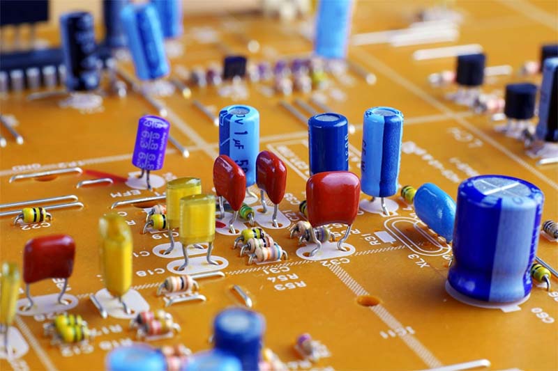
Aluminum Electrolytic Capacitor vs Ceramic
Different capacitor types offer different combinations of capacitance, ESR, size, voltage rating, lifetime, and performance. While aluminum electrolytic capacitors and ceramic capacitors (MLCCs) are two of the most widely used types, aluminum polymer, film, and supercapacitors also have their own advantages for specific applications. The following table compares these five capacitor types to help you understand their key differences and choose the right capacitor for your application.
|
Capacitor Type |
Advantages |
Disadvantages |
ESR |
Capacitance |
Main Applications |
|
Aluminum Electrolytic Capacitors |
High capacitance, low cost |
Polarized, limited lifetime |
MediumF-High |
µFF - mF |
Power filtering, energy storage, DC-link |
|
Aluminum Polymer Capacitors |
Low ESR, high ripple current, long life |
Higher cost, lower voltage range |
Low |
µF - mF |
DC/DC converters, power supplies, CPU/VRM |
|
MLCC |
Compact, low ESR/ESL, high-frequency performance |
DC bias effect, cracking risk |
Very Low |
pFF - 100s µF |
Decoupling, RF, high-frequency filtering |
|
Extremely high capacitance, long cycle life |
Low voltage, high leakage current |
Low |
FF - 1000s F |
Backup power, energy storage, regenerative systems |
|
|
Film Capacitors |
Stable, reliable, low loss |
Large size, lower capacitance density |
Very Low |
nFF - 100s µF |
Power electronics, snubbers, AC filtering |
- Aluminum Electrolytic: High capacitance at a low cost.
- Aluminum Polymer: Lower ESR and better ripple-current performance.
- Film: Excellent stability, reliability, and low loss.
- Super Capacitor: Extremely high capacitance for energy storage.
- MLCC: Compact and excellent for high-frequency applications.
How to Choose Aluminum Electrolytic Capacitor for Circuit Design
Aluminum electrolytic capacitors are widely used for power-supply filtering, energy storage and DC-link applications. Proper component selection and circuit design are critical to avoid premature failure, excessive heat and circuit performance degradation.
Capacitance
Select capacitance value based on required hold-up time, ripple suppression target and load current. Too small capacitance leads to large output ripple; over-specifying capacitance increases size, cost and inrush current. Note that actual capacitance decreases at low temperature. Always consider capacitance tolerance and low-temperature derating.
Rated Voltage
Operating voltage must stay below capacitor rated voltage. Voltage derating is recommended: keep continuous working voltage at 70 %-80 % of rated voltage for general commercial applications; for industrial environments with surge, limit to 60 %-70 %. Never apply reverse voltage, even transient reverse bias may destroy the oxide dielectric layer.
Ripple Current & ESR
Equivalent Series Resistance (ESR) generates heat when ripple current flows through the capacitor. Exceeding rated ripple current causes internal overheating, accelerates electrolyte evaporation and shortens service life.
- Low ESR versions should be chosen for high-ripple circuits.
- Multiple capacitors in parallel can share ripple current and reduce overall ESR.
- Avoid stacking excessive ripple current margin only by increasing capacitance value.
Temperature Rating
Ambient temperature directly determines lifetime. Select components matching the maximum ambient temperature inside the enclosure. Remember that self-heating from ripple current adds extra temperature rise above surrounding air temperature. Higher operating temperature drastically reduces expected service life.
Circuit Design Considerations
Polarity Protection
Strictly maintain correct anode‑cathode connection. Reverse voltage will trigger gas generation, swelling or catastrophic rupture. For circuits where reverse voltage may occur, add reverse-protection diodes or choose non-polarized electrolytic types.
Inrush Current Limiting
Large-value electrolytic capacitors draw high surge current during power-on. This may damage rectifiers, switches and connectors. Implement NTC thermistors or active inrush-limiting circuits to suppress startup current.
Parallel and Series Connection
Parallel: Increases total capacitance and ripple-current handling capability. Match component impedance to ensure even current sharing.
Series: Achieve higher total withstand voltage. Balancing resistors are mandatory to avoid uneven voltage distribution across individual capacitors. Series connection is generally avoided whenever possible for aluminum electrolytics.
Layout and Thermal Design
- Place electrolytic capacitors close to power ICs or rectifier outputs to minimize trace inductance.
- Keep high-current loops short to reduce additional voltage ripple.
- Avoid positioning capacitors near heat sources such as power resistors or transformers. Maintain sufficient air flow for cooling.
- Do not cover capacitor vent structures, ensure space for possible gas release.
Surge and Transient Handling
Voltage spikes from switching, load dump or inductive kick can damage capacitors. Add TVS or RC snubber networks to clamp transient over-voltage when working in harsh industrial environments.
For high-reliability requirements: combine aluminum electrolytic capacitors with small-value MLCC in parallel. Electrolytics provide bulk energy storage and low‑frequency filtering; MLCC suppress high-frequency noise, reduce overall system impedance.
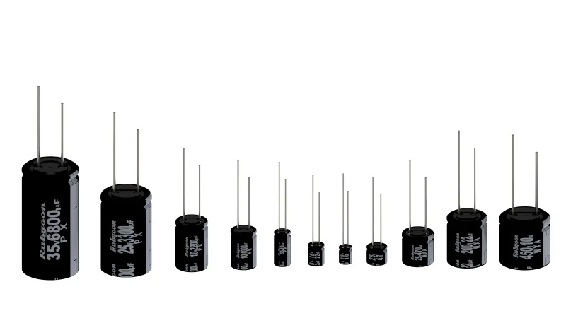
The Leading Capacitor Authorized Distributor
We offer a wide selection of capacitors from leading manufacturers, covering multiple capacitor types, specifications, and package options.
Wide Range of Capacitor Types
Our capacitor portfolio includes aluminum electrolytic capacitors, ceramic capacitors (MLCCs), aluminum polymer capacitors, film capacitors, and supercapacitors. With a broad selection of capacitance, voltage, tolerance, and package specifications, we can support different circuit and application requirements.
Aluminum Electrolytic Capacitor Alternative
If your required aluminum electrolytic capacitor has been discontinued, become difficult to source, or increased significantly in price, we can help you find suitable alternative or replacement models. Based on key specifications such as capacitance, rated voltage, tolerance, ESR, ripple current, package size, and operating temperature, we can identify compatible options from different manufacturers to help maintain your supply and control costs.
Your Reliable Capacitor Sourcing Partner
With access to multiple brands and thousands of capacitor models, we can help you source the components you need for power supplies, industrial equipment, automotive electronics, consumer electronics, and other applications. Tell us your required capacitor specifications or part number, and we can help you find a suitable solution.
The Bottom Line
When an aluminium electrolytic capacitor no longer fits a design because of space, frequency, lifetime, or sourcing requirements, looking for an aluminum electrolytic capacitor alternative can open up more suitable options. The key is to compare the electrical and environmental requirements of the circuit rather than replacing the component based on capacitance alone. This approach helps engineers balance performance, reliability, and availability while adapting the design to different application needs.
Related information
- 2026.08.16 What are BJT and MOSFET Transistors?

- 2026.07.28 What are Programmable Logic Controllers?
- 2026.07.26 What is a Ceramic Capacitor?
- 2026.07.21 What is Inductor and Inductance?